Disclaimer. The author doesn’t bear any responsibility for any consequences related to the device described in this article, including a lost profit. Decisions made by a reader are implemented at his own risk.
Our company has a remote server connected to the WWW via a wireless modem. The wireless modem is connected to a router. Sometimes the modem cancels the connection without any reasons. Router reset doesn’t give any result, and only the manual turning off of the modem helps to restart it.
As we need to get access to the server even there’s nobody near it, we have to restart the modem automatically. By the way, I heard that miners had the same problems with an internet connection.There’re some solutions on the internet one can find. For example:
- USB-relay. But you’d have to make a program to control it;
- IP WatchDog and similar devices. But they are too expensive for this simple job;
- DIY devices. But they use microcontrollers that you have to program too.
- User don’t have to program;
- Can be built by anyone;
- Costs almost nothing.

When something is transmitting the COM-port (I used a USB/TTL COM-port converter) it causes some pulses on the TX pin. These pulses induce the start of the long pulse of the 555 chip scheme, which controls the relay that disconnects modem power supply for some seconds. The power for this scheme takes from the USB connector.
The components shown in the scheme are that I had. You can use your own components. For example, IRFZ44N is more than enough for this device, but I had a lot of them. So, you can use other MOSFETs or even bipolar or Darlington transistors. But if you use bipolar or Darlington ones you should replace the relay with one with 4.5V coil and increase the resistance of R2 up to 1-2 kOhms.
You can even use a more powerful relay. But if the relay has coil resistance below 100 Ohm, you should use separate power supply unit to not overload a USB port.
I used a CP210X-based USB/TTL COM-port converter. And it gives negative pulses of TX (3.3-0-3.3V). If your converter gives positive pulses (0-5-0)V, you should use the following input and 555 scheme:

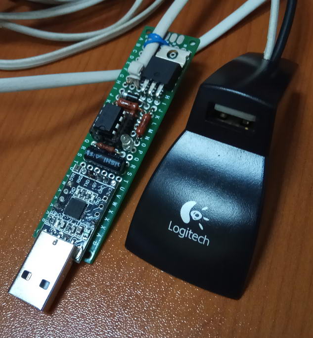
This device was built on a small prototype PCB for inserting directly to the computer USB port.


| @Echo Off SetLocal EnableExtensions EnableDelayedExpansion :Begin ping google.com If !ErrorLevel! == 0 ( Echo Internet Online ) Else ( Echo Internet Offline Echo rebooting modem... copy win.ini >com5 ) Timeout /t 180 /nobreak >nul Goto Begin |
File ‘win.ini’ was chosen as it’s a tiny file and it’s available from any folder. So, you can place your .bat or .cmd file in any folder you want.
If you don’t want to run this file infinitely, you can delete :Begin, Timeout<> and Goto<> commands from the file and run it by the schedule of the Task Scheduler.
I even heard that .bat or .cmd files are able to run in the hidden mode, but I didn’t try it as I didn’t need it. So, you can find out how to do that by yourself.
Anyway, you can control other stuff with this device by making your own .bat file with your own conditions. You can insert several devices and get control on several channels. So, that’s the idea only, you can apply it to any of your own DIY devices.


